
Decal Project
shortcut dd1
On curved surfaces just snapping a flat, single-quad decal to the surface may not quite produce the desired effect. This is where Decal Project comes in: A decal or group of decals can be selected and be projected to a target object, matching the target surface and topology precisely.
Decal Project will automatically assign a base material to the projection target, if there's no existing material.
 shadows added for emphasis
Properties

Projection Depth
Determines the depth of the projection - how far along the Decal's local z axis(positive and negative) the projection reaches.
A value too high may create a decal on the front and backside of the mesh you are projecting on.
A value too low may create a smaller-than-expected or cropped projected decal or may result in the projection failing.
Decal Height
Controls the amount a decal is offset from the underlying surface. The Decal Height can be controlled using the Adjust Decal Height tool at a later stage as well.
Parent
Parents the projected Decal to the target object.
Transfer Normals
Adds a data transfer modifier to the decal using the target object as a normals source.
See (W)Step for details.
Topo Slice
shortcut ds(with 2 objects selected)
Topo Slicing is very similar in execution as 'c-slicing'/'c-slashing' is done in HardOps - if you are familiar with that - or when doing a boolean operation, but it's completely different in terms of results. Instead of actually cutting a mesh in pieces and beveling newly created edges, the target mesh stays completely untouched and a decal panel strip is created at the intersection of target geometry and cutting object. Just like regular decals, panel decals float very slightly above the surface. Automatic UV creation and material application result in a visually indistinguishable panel cut.
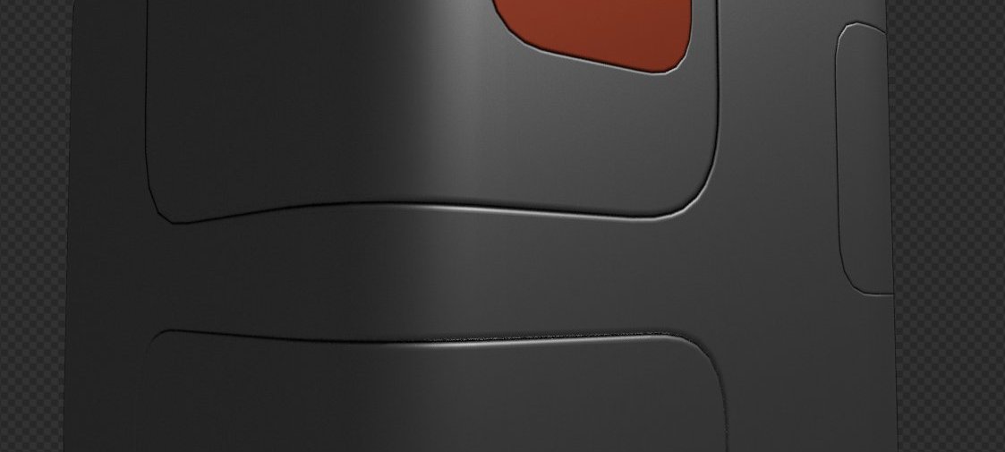 only one of these cuts is 'real', which one?
Topo Slicing, just like Decal Projecting is completely non-intrusive and does not affect the underlying surface's shading in any way.
And just like Decal Project, Topo Slice will re-create the target objects topology exactly - thereby ensuring a very precise fit.
Tip
You can choose the panel decal type before slicing, by choosing a Slice/Knife default from the dropdown in the pie menu.
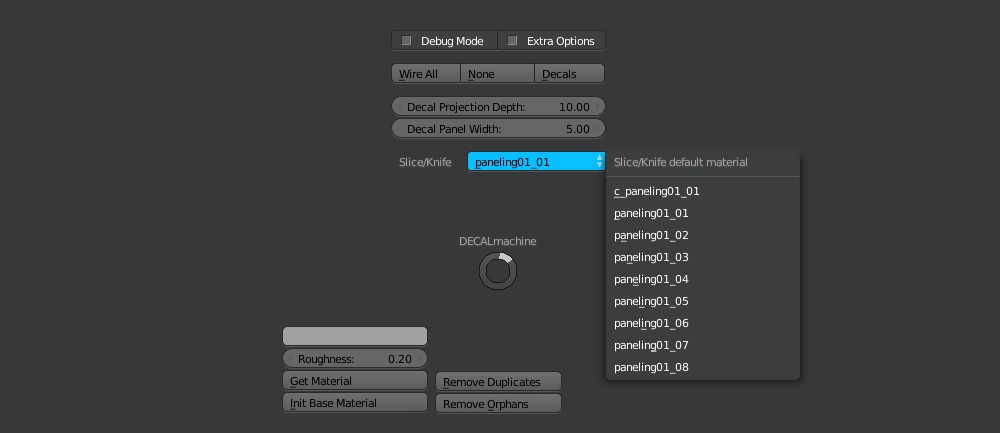
You can change the panel decal type of an existing panel decal, by assigning a new decal material.
Topo Slice will automatically assign a base material to the slice target, if there's no existing material.
Properties

Panel Width
Controls the width of the panel decal strip. The Panel Width can be controlled using the Change Panel Width tool at a later stage as well.
Decal Height
Controls the amount a decal is offset from the underlying surface. The Decal Height can be controlled using the Adjust Decal Height tool at a later stage as well.
Twist Offset
Just like on Blender's Bridge tool, adjusts the twist offset, which can be usefull if a panel strip's boundary edge loops don't line up properly.
Rotate UVs
Rotates panel strip UVs by 90 degrees, used to fix the occasional faulty UVs in panel strips.
Flip Normals
If checked, inverts the normal directions of the decal - usefull when slicing on the insides of an assets.
Parent
Parents the sliced Decal to the target object.
Transfer Normals
Adds a data transfer modifier to the decal using the target object as a normals source.
See (W)Step for details.
Tip
If Topo Slice fails to create a properly textured decal panel strip, lower the Panel Width in the operator properties.
Atlernatively, un-doing and moving the cutting object slightly can also resolves issues. It's also a good idea to turn on the wireframes to evaluate troublesome areas.
The Reason Topo Slice sometimes will fail is because an all-quad panel strip could not be created due to overlappying or intersecting edges.
Topo Knife
shortcut dk
Topo Knife is a modification of Topo Slice. Whereas Slicing is to be used with cuts going through the entire target object and thereby creating a closed panel decal loop, Knifing is for cuts that go in, but not through, creating an open panel strip.
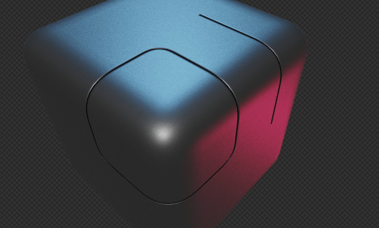 Slice vs Knife
Properties

Panel Width
Controls the width of the panel decal strip. The Panel Width can be controlled using the Change Panel Width tool at a later stage as well.
Decal Height
Controls the amount a decal is offset from the underlying surface. The Decal Height can be controlled using the Adjust Decal Height tool at a later stage as well.
Rotate UVs
Rotates panel strip UVs by 90 degrees, used to fix the occasional faulty UVs in panel strips.
Flip Normals
If checked, inverts the normal directions of the decal - usefull when slicing on the insides of an assets.
Parent
Parents the knifed Decal to the target object.
Transfer Normals
Adds a data transfer modifier to the decal using the target object as a normals source.
See (W)Step for details.
Float Slice
shortcut df (with two objects selected)
Float Slice is an alternative tool to create panel decal strips using a different method to arrive at the strip geometry.
Unlike Topo Slice, it is guaranteed to always generate proper all-quad strips, even on dense geometry. Its topology is pseudo-independent of the targets topology.
Float Slice is best used on dense geometry, while Topo Slice is best used on low poly geo.
 Trying to follow the underlying edge flow, Topo Slice can produce angled edges or worse produce tris and fail completely. Float Slice produces quads guaranteed.
If you are using Float Slice on low poly geometry, it will usually need need more Decal Height compared to Topo Slice to avoid intersecting with the surface below, as the panel geometry doesn't follow the topology closely.
A panel strip created by Float Slice comes with a Shrinkwrap modifier by default. This is helpful in case you want to manually add or edge edges to better conform to the underlying surface.
As a result of the different method to create the panel strip, Float Sliced panels can be uneven in their width across the length of the strip, and the Panel Width value should be understood as an approximation, not a precise meassure.
The Average Edge Length property in the F6 panel/operator panel tries to alleviate this, but can be slow.
Properties

Panel Width
Controls the width of the panel decal strip. The Panel Width can be controlled using the Change Panel Width tool at a later stage as well.
Decal Height
Controls the amount a decal is offset from the underlying surface. The Decal Height can be controlled using the Adjust Decal Height tool at a later stage as well.
Simplify
Merges vertices, that are close to eachother to remove redundant geometry. Increase the value to increase the distance of vertices to merge.
Density
Subdivides the panel strip length wise, thereby adding more geometry uniformly.
Offset
Slides the panel strip inwards or outwards. A downside of Float Slice is that it isn't always positioned precisely where the cutting object intersects the target. Offset can be used to compensate for this, but its experimental and doesn't always work.
Rotate UVs
Rotates panel strip UVs by 90 degrees, used to fix the occasional faulty UVs in panel strips.
Flip Normals
If checked, inverts the normal directions of the decal - usefull when slicing on the insides of an assets.
Parent
Parents the sliced Decal to the target object.
Average Edge Length
If activated, equalizes each edge contributing to the panel width.
Transfer Normals
Adds a data transfer modifier to the decal using the target object as a normals source.
See (W)Step for details.
Draw Slice
shortcut ds (with one object selected and active)
Draw Slice is a precursor tool intended to be used with Float Slice.
First, select a single object and call Draw Slice. This puts you in a mode where you can "draw" edges on the surface by extruding vertices. See the viewport OSD at the bottom right corner of the 3D View for details.
Once done, press ´Tab´ to finish Decal Slice, followed by ´df´ to run Float Slice.
Panelize
shortcut dp
Panelize turns Polygons into Panel Decals. In cases of simple geometric shapes this is often a faster and easier method to create a decal strip compared to slicing or drawing.
Properties

Panel Width
Controls the width of the panel decal strip. The Panel Width can be controlled using the Change Panel Width tool at a later stage as well.
Decal Height
Controls the amount a decal is offset from the underlying surface. The Decal Height can be controlled using the Adjust Decal Height tool at a later stage as well.
Invididual
If checked multiple panel strips will be created. This depens on the existing topology, meaning you can control where individual strips are created by cutting eges. The Gap value determins the amount of separation.
Bevel
If checked, the corners will be beveled according to the Amount and Segments.
Rotate UVs
Rotates panel strip UVs by 90 degrees, used to fix the occasional faulty UVs in panel strips.
Flip Normals
If checked, inverts the normal directions of the decal - usefull when slicing on the insides of an assets.
(A)Material Decal
shortcut da (with two objects selected)
Material Decals are a non-intrusive way to assign different materials to different parts of a model. They are created using the same boolean-like methodology as in Decal Slicing. Just like regular decals, they float a minuscule amount above the target object and unlike regular decals, they tend to(but don't have to) cover big sections of the target mesh. Material Decals can then of course also serve as target meshes for other decals.
Tip
All decals can essentially be 'stacked' on top of each other. When you stack decals on decals that are parallax mapped, it's sometimes a good idea(depends on the decal) to turn off the parallax for that specific decal. Not doing so, may introduce a 'swimming' effect, where depending on the camera angle, the stacked decal may not seem to be in the position you intend it to be.
Properties

Decal Height
Controls the amount a decal is offset from the underlying surface. The Decal Height can be controlled using the Adjust Decal Height tool at a later stage as well.
Parent
Parents the Material Decal to the target object.
Transfer Normals
Adds a data transfer modifier to the decal using the target object as a normals source.
See (W)Step for details.
(W)Step
shortcut dw
Note
(W)Step is meant to be used alongside HardOps and its Boolean tools. Also see Hardops Fix.
While you can use (W)Step without HOps, you will have to manually turn off (W)Step visibility(Data Transfer mod) after doing a boolean operation or face shading issues obstructing your view of the mesh topology.
Borrowing terminology from HardOps, (W)Step will take an object with a live Bevel modifier, apply the bevel mod with 1 segment - thereby chamfering it - and create custom vertex normals to create smooth shading acrross the chamfered edge, creating a fake a fillet, with minimal geometry.
This is achieved using a wstep material, that's automatically created and applied to the bevel geometry, which in turn marks the polygons that won't contribute to the smoothing. Without the bevel geometry contributing, the smoothing is interpolated between the non-bevel geo. A DataTransfer modifier called "M3_custom_normals" is used to create the custom normals.
Keep in mind
(W)Step works using a Data Transfer modifier. There might be situations where you want to toggle the modifier's visibility - at least until you render or export - as it has a tendency to slow down the viewport.
Furthermore, it's generally a good idea to have the data transfer modifier at the end of the stack. If you are using the MACHIN3tools Mirror tool, it will automatically move the data transfer mod behind the mirror mod.
Tip
If you ever notice the shading behaving unexpectedly, but have confirmed, that all the chamfers have received a wstep material(see below), then it's usually due to (W)Steps's data tranfer mod not being at the end of the modifier stack or the normal source mesh not being updated. Just run (W)Step again in this case.
Edit Mode
You may prefer to manually define the edgesTo really fine tune or fix potential wstep issues, you can call it edit mode as well, in wich case (W)Step will assign/remove the wstep material for the selected polygons
Tip
To visualize the wstep material I recommend using the MACHIN3tools Red Mode and the Shading Switch.
Shading Switch allows to quickly switch from Solid to Material shading. Red Mode - with Material shading active - will toggle the wstep material red.
Transfer Normals
There's a third modus operandi, by firing (W)Step on a slection of 2+ objects, in which case the smoothing of the active object is transfered to the selected objects.
By default, this mode of (W)Step is called automatically by Decal Project, Topo Slice and Float Slice.
Properties

Type
Select the DataTransfer method used to map source values to the destination. Check out the Blender docs for the DataTransfer modifier for details. Also note the Allow Hard Edges option.
Allow Hard Edges
WStep's "M3_custom_normals" DataTransfer modifier uses the "Nearest Face Interpolated" method to map normal vectors from the source mesh. This is a great default, if you'll also have material seams in the mesh, that shouldn't contribute the the normals. Unfortunalte it doesn't allow for hard edges in the model. If you tick this option, a second DataTransfer modifier "M3_hard_custom_normals' will be created using the "Nearest Corner and Best Matching Face Normal" mmethod will be used. This takes hard edges into account, but won't play well with material seam edges, and so it is masked by a hard_edges vertex group.
Show in Viewport
Determines the visibility state of the Data Transfer modifier in the viewport.
Data Transfer can slow down the viewport considerably and so you might want to add it, but not display it while actively working on an asset.
Tip
Use MACHIN3tools Mod Machine to toggle the visibility of Data Transfer mods in bulk on multiple objects.
Edit/Commit Normal Source
shortcut de (Edit)
shortcut dc (Commit)
Edit/Commit Normal Source is a companion tool to W(Step) used to quickly access the normal source mesh used by the "M3_custom_normals" DataTransfer modifier. Edit Normal Source is available in Object Mode when a WStepped object is active. Commit Normal Source is available in Object Mode when a Normal Source mesh is active.
You may want to edit the normal source if you want to remove Material Cut edges from the source mesh.
Surface Fix
shortcut ds (Edit Mode)
Extending on the WStep custom normal workflow, Surface Fix can be used to remove unwanted shading artefacts. This is achieved by maintaining a separate surface source mesh(just like WStep) and transferring its normal information to vertices masked by a vertex group.
Surface Fix is called in Edit Mode, with a selection of the vertices to be affected by the tool. A vertex group with the selction will be created, which is in turn used to mask of the DataTransfer modifier created by Surface Fix.
Tip
You can edit the surface_fix vertex group used to mask the "M3_surface_fix" DataTransfer modifier at any latert point.
Edit/Commit Surface Fix
shortcut de/df (Edit, depending on the presence of a "M3_custom_normals" modifer)
shortcut dc (Commit)
Edit/Commit Surface Fix is a companion tool to Surface Fix used to quickly access the normal source mesh used by the "M3_surface_fix" DataTransfer modifier. Edit Normal Source is available in Object Mode when a Surface Fixed object is active. Commit Normal Source is available in Object Mode when a Surface Fix Source mesh is active.
-
In the case of
dd, you need to also click with the mouse afterwards, otherwise the pie will stay open, as it is triggered with the seconddas well, unfortunately. ↩